How to pump the Necam Camera
NECAM PUMPING
The table below provides details of the pumping time. Task 1.23 should last a minimum of 7 hours and should be extended to the maximum. The exact duration of this task depends on the start time of the ECAM flats.
The task 1.27 must start 3 hours before the beginning of the flats
| ID | Description | Duration |
|---|---|---|
| 1.1-1.17 | Preparation | 15 min |
| 1.18 | Pipe pumping | 30 min |
| 1.19-1.26 | Hot camera pumping | >430 min (to be adjusted) |
| 1.27-1.34 | Cooling of the camera | 150 min (2h30) |
| 1.35 | Switching off of the pump | 10 min |
| 1.36-1.46 | Storage | 15 min |
| TOTAL | 650min (10h50) |
OPERATIONS
1.1 Check that the telescope is in park position
1.2 Remove the yellow protective cover from the pump unit
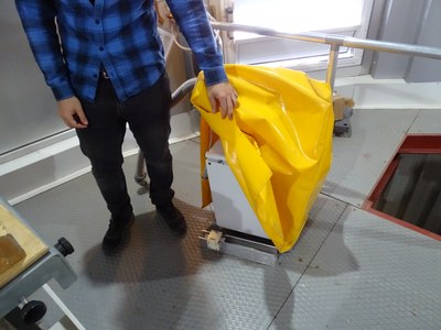
1.3 Remove the safety lock
Comment: this security prevents the telescope from moving
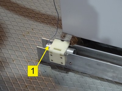
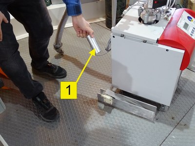
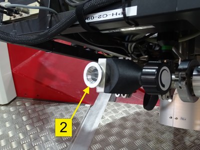
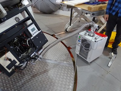
1.4 Unlock the brake on the wheels of the pumping unit and move it so that the pipe can be connected to the pumping interface of the camera without tension ②
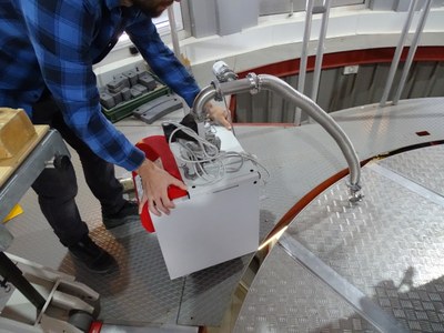
1.5 Switch on the touch screen at the top of the stairs with the switch on the side of the electronic box on the right side of the screen (Ignition time is several seconds)
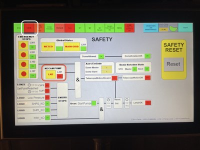
1.6 Check that the Safety button on the top of the touch screen is red
Comment: a red safety button means that the safety lock is removed and that the telescope can not be moved
1.7 Remove the metal covers of the camera pump interface ② and the pumping unit ③
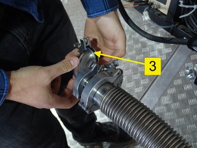

1.8 Store the covers on the pump unit
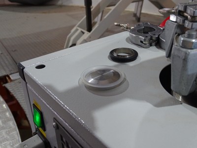
1.9 Adjust the position of the pump unit to connect the pump unit hose ③ at the pumping interface of the camera ②.
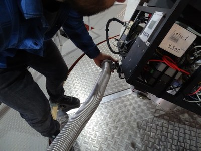
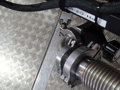
(1.10)-1.11 Connect the power supply cable of the pump unit to the UPS socket
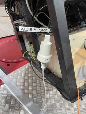
1.12 Here is the position of the pumping unit once connected to the camera

1.13 Lock the brake on the wheels of the pump unit
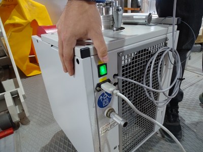
1.14 Switch on the pump unit with the switch
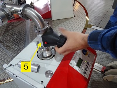
1.15 After starting the pump unit controller, press button no. 6 to start pumping and immediately open the valve at the pump unit outlet ⑤ counterclockwise.
DO NOT OPEN THE VALVE ON THE CAMERA SIDE
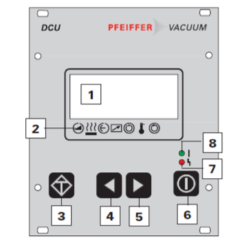
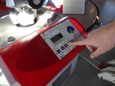
1.16 Record the pump start time
1.17 Use arrow buttons n°4 and n°5 to display the value 340 on screen n°1

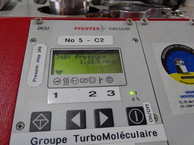
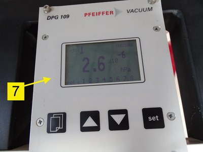
1.18 Wait until the pressure on the pump unit is below the pressure in the camera (DPG109 monitor on telescope) :
- pump unit reaches 1 mbar in ~1min
- pump unit reaches 2E-5 mbar in ~30min

1.19 Open the camera valve ⑥ by turning counterclockwise
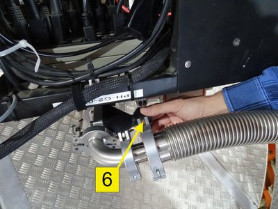
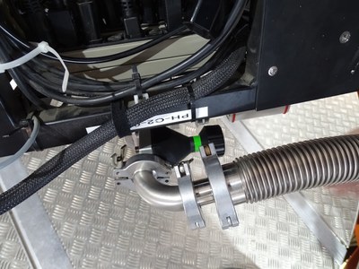
1.20 Record the valve opening time
STOPPING THE CRYOCOOLER
AT THIS TIME CONTACT THE PERSONS HAVING ACCESS TO THE EULER COMPUTERS (Localy or in Geneva)
The following steps can only be done with an account on the Euler computers
When the pumping is finished (with the local or Geneva agreement) continue with 1.31
1.21 Go down to the control room (for local people!)
1.22 Log on glslogin1 (x2go for Geneva people), and from there on glsserv02 with:
ssh -XY euler@glsserv02
1.23 Run the following commands
Nstop_CC
Nlakeshore -C 50
1.24 After 2 minutes, check on the display giving the status of the instruments that the set temperature of the CCD is at 50°C(in the Control Room)
You can also type:
control_temp_azote.pl
1.25 On glslogin1 run:
meulplot is a display tool allowing to monitor the pressure (and more).
meulplot
then:
  select "Necam" tab
  select "Pression"
  set the checkbox "AutoAdjust"
  click on "Plot" will refresh the plot
  you can change the time scale in "Predefines Choices"
  you can see the pressure to reach by setting the checkbox "Limits"
The following pressure curves were observed during previous pumping operations:
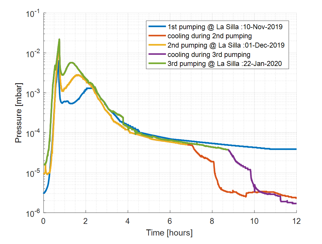
1.26 Wait until you reach <5x10⁻⁵ mbar on the DPG109 monitor (~7h)
1.27 Cool the camera: run the command
Nstart_CC
comment 1 : it may be necessary to connect to euler@glsserv02 again
comment 2 : it is normal for the pressure to drop
1.28 Record the start time of the cooling process
1.29 Wait until Nstart_CC command is completed
1.30 Record the Time
STOPPING PUMPING
1.31 Close the valve of the camera ⑥ by turning it clockwise and do not force it excessively

1.32 Close the valve at the outlet of the pump unit ⑤ in clockwise direction

1.33 Press button n°6 to stop pumping (~15min)


!!!! DO NOT MOVE THE PUMP UNIT BEFORE 0 [Hz] (see below)
1.34 With the arrow buttons n°4 and n°5, display the value 309 on screen n°1 to see the rotation frequency of the turbomolecular pump

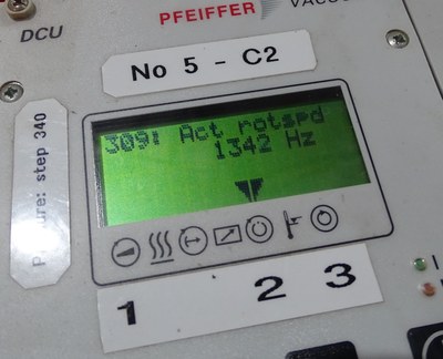
1.35 Once the speed has reached 0Hz (~10min), turn off the pump unit with the rear switch

1.36 Check on the DPG 109 ⑦ that the pressure remains lower than 5*10-6mbar.
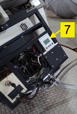
1.37 Disconnect the pump pipe (it is normal to have to break the vacuum in the pump pipe)
1.38 Install the protective cover with the o-ring and clamp on the pump pipe ③
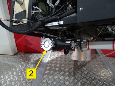
1.39 Install the protective cover with o-ring and clamp on the pump outlet of the camera ②
!!!! ORIENT THE CLAMP AS SHOWN BELOW
1.40 Disconnect the power cable
1.41 Unlock the brake on the wheels of the pump unit
1.42 Store the pumping unit in the following location and reinstall the safety lock


1.43 Lock the brake on the wheels of the pump unit
1.44 Install the yellow protective cover

1.45 Check that the Safety button on the touch screen at the top of the stairs is green
Comment: a green safety button means that the safety lock and the pump are in place and that the telescope can be moved
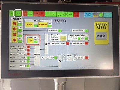
1.46 Turn off the touch screen at the top of the stairs with the switch on the side of the electronic box (on the right of the screen)
