Hardware.html
Sommaire
1. Environment
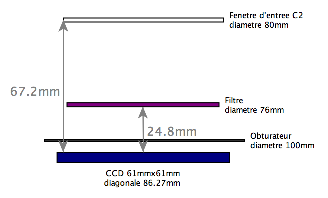
- taille filtre obturateur C2/ nouveau CCD
1.1. CCD array
-
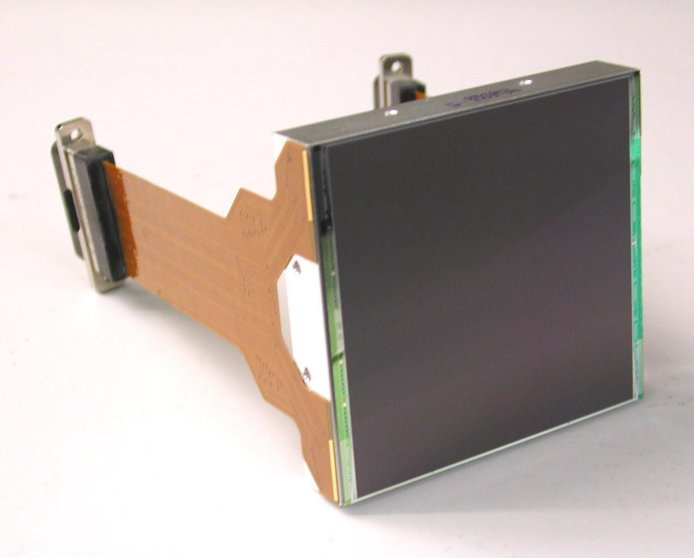
- CCD231-84 Back Illuminated Scientific CCD Sensor
- 4096 x 4112 Pixels, Four Outputs,
- Non-inverted Mode Operation
- Reference CCD231-84-1-E06: Grade 1, Deep depletion silicon, astro-ER1 coated
1.1.1. Performances summary (Typical)
-
Number of pixels
4096(H) x 4112(V)
Pixel size
15 μm square
Image area
61.4 mm x 61.4 mm
Outputs
4
Package size
63.0 x 69.0 mm
Package format
silicon carbide with two flexi connectors
Focal plane height, above base
15.0 mm
Height tolerance
±10 μm
Connectors
two 37-way micro-D
Flatness
<20 μm (peak to valley)
Amplifier sensitivity
7 μV/e−
Readout noise
5 e− at 1 MHz / 2 e− at 50 kHz
Maximum pixel data rate
3 MHz
Charge storage (pixel full well)
350,000 e−
Dark signal
3 e−/pixel/hour (at –100 °C)
Grade 1
Guaranteed
Typical
Description
White spots
800
<400
A defect is counted as a white spot if the dark generation rate is ≥ 5 e-/pixel/s at 173 K. (which is also equivalent to ≥100 e-/hour at 153 K). The temperature dependence is the same as for the mean dark signal.
Column defects - black or white
10
<3
A column is counted as a defect if it contains at least 100 white or dark single pixel defects.
Total (black & white) spots
1500
<750
A black spot defect is a pixel with a photo-response less than 50% of the local mean.
Traps > 200e-
15
<10
A trap causes charge to be temporarily held in a pixel and these are counted as defects if the quantity of trapped charge is greater than 200 e-
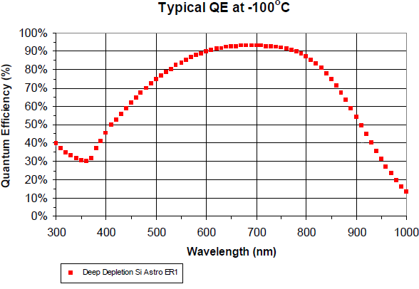
1.1.2. Spectral response
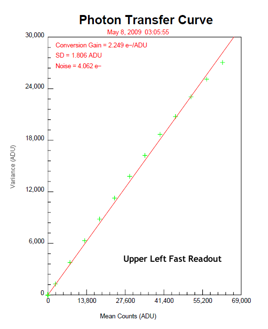
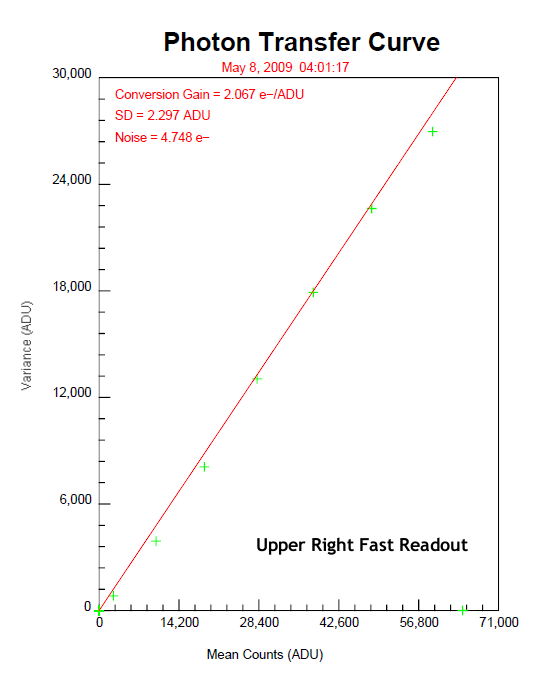
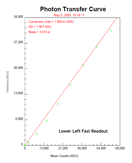
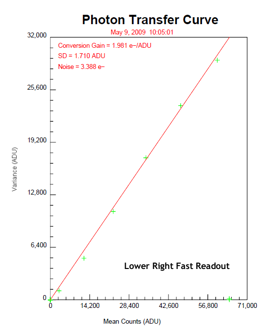
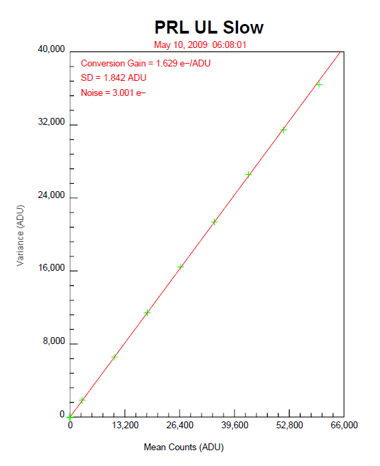
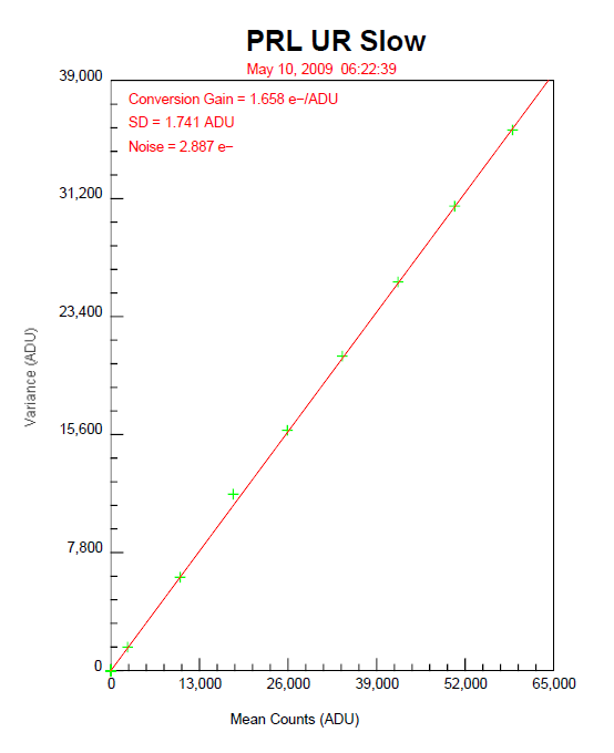
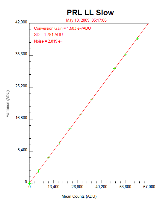
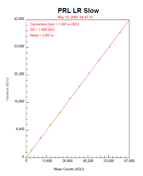
1.1.3. Photon Transfer Curves
1.1.4. Output line format
1.1.5. Full Datasheet/Specifications
1.1.6. Wiring List
|
CCD Preamp |
Wire |
Dewar |
Controller |
Clk Dr. |
VIDEO-0
|
VIDEO-1
|
Utility |
Wire |
Signal |
||
| Pin # Board | Type | Wire AWG | MS-61 Male | DB-37 | DB-9 | DB-25 | DB-9 | DB-25 | Aux | AWG | Name |
|
DB2 #31 |
Coax |
Coax |
A |
|
1 |
|
|
|
|
RG-174 |
VID_LL |
|
DB2 #30 |
Shield |
Shield |
b |
|
9 |
|
|
|
|
|
Shield |
|
DB1 #1 |
Coax |
Coax |
a |
|
8 |
|
|
|
|
RG-174 |
VID_ LR |
|
DB1 #2 |
Shield |
Shield |
Z |
|
15 |
|
|
|
|
|
Shield |
|
DB1 #17 |
Coax |
Coax |
Y |
|
|
|
1 |
|
|
RG-174 |
VID_ UR |
|
DB1 #18 |
Shield |
Shield |
u |
|
|
|
9 |
|
|
|
Shield |
|
DB2 #16 |
Coax |
Coax |
c |
|
|
|
8 |
|
|
RG-174 |
VID_ UL |
|
DB2 #15 |
Shield |
Shield |
B |
|
|
|
15 |
|
|
|
Shield |
|
|
|
|
|
|
|
|
|
|
|
|
|
|
DB1 #12 |
Const. |
26GA |
T |
13 |
|
|
|
|
|
22GA |
I1_L |
|
DB1 #13 |
Const. |
26GA |
p |
14 |
|
|
|
|
|
22GA |
I2_L |
|
DB2 #20 |
Const. |
26GA |
i |
15 |
|
|
|
|
|
22GA |
I3_L |
|
DB2 #4 |
Const. |
26GA |
K |
16 |
|
|
|
|
|
22GA |
I4_L |
|
DB2 #21 |
Const. |
26GA |
J |
17 |
|
|
|
|
|
22GA |
TG_L |
|
DB1 #10 |
Const. |
26GA |
S |
1 |
|
|
|
|
|
22GA |
RG |
|
DB2 #27 |
Const. |
26GA |
e |
|
|
3 |
|
|
|
22GA |
Vrd_LL |
|
DB2 #28 |
Const. |
26GA |
D |
|
|
1 |
|
|
|
22GA |
Vod_LL |
|
DB2 #26 |
Const. |
26GA |
x |
|
|
9 |
|
|
|
22GA |
Vog_LL |
|
DB2 #24 |
Const. |
26GA |
H |
8 |
|
|
|
|
|
22GA |
SW_LL |
|
DB2 #22 |
Const. |
26GA |
k |
2 |
|
|
|
|
|
22GA |
R1_L |
|
DB2 #7 |
Const. |
26GA |
L |
3 |
|
|
|
|
|
22GA |
R2_L |
|
DB2 #23 |
Const. |
26GA |
j |
4 |
|
|
|
|
|
22GA |
R3_L |
|
DB2 #8 |
Const. |
26GA |
G |
9 |
|
|
|
|
|
22GA |
SW_UL |
|
DB1 #5 |
Const. |
26GA |
s |
|
|
4 |
|
|
|
22GA |
Vrd_LR |
|
DB1 #4 |
Const. |
26GA |
W |
|
|
2 |
|
|
|
22GA |
Vod_LR |
|
DB1 #6 |
Const. |
26GA |
FF |
|
|
10 |
|
|
|
22GA |
Vog_LR |
|
DB2 #6 |
Const. |
26GA |
AA |
18 |
|
|
|
|
|
22GA |
I1_U |
|
DB1 #29 |
Const. |
26GA |
CC |
19 |
|
|
|
|
|
22GA |
I2_U |
|
DB1 #28 |
Const. |
26GA |
n |
33 |
|
|
|
|
|
22GA |
I3_U |
|
DB1 #27 |
Const. |
26GA |
DD |
34 |
|
|
|
|
|
22GA |
I4_U |
|
DB2 #5 |
Const. |
26GA |
z |
35 |
|
|
|
|
|
22GA |
TG_U |
|
DB1 #21 |
Const. |
26GA |
t |
|
|
|
|
3 |
|
22GA |
Vrd_UR |
|
DB1 #20 |
Const. |
26GA |
X |
|
|
|
|
1 |
|
22GA |
Vod_UR |
|
DB1 #22 |
Const. |
26GA |
GG |
|
|
|
|
9 |
|
22GA |
Vog_UR |
|
DB1 #9 |
Const. |
26GA |
P |
10 |
|
|
|
|
|
22GA |
SW_LR |
|
DB1 #11 |
Const. |
26GA |
M |
5 |
|
|
|
|
|
22GA |
R1_R |
|
DB1 #26 |
Const. |
26GA |
N |
6 |
|
|
|
|
|
22GA |
R2_R |
|
DB1 #25 |
Const. |
26GA |
m |
7 |
|
|
|
|
|
22GA |
R3_R |
|
DB1 #24 |
Const. |
26GA |
R |
11 |
|
|
|
|
|
22GA |
SW_UR |
|
DB2 #12 |
Const. |
26GA |
d |
|
|
|
|
4 |
|
22GA |
Vrd_UL |
|
DB2 #13 |
Const. |
26GA |
C |
|
|
|
|
2 |
|
22GA |
Vod_UL |
|
DB2 #11 |
Const. |
26GA |
w |
|
|
|
|
10 |
|
22GA |
Vog_UL |
|
DB2 #3 |
Const. |
26GA |
KK |
|
|
5 |
|
|
|
22GA |
Vdd_L |
|
DB1 #14 |
Const. |
26GA |
EE |
|
|
|
|
5 |
|
22GA |
Vdd_U |
|
DB2 #19 |
Const. |
26GA |
h |
36 |
|
|
|
|
|
22GA |
DG |
|
DB1 #8 |
Copper |
26GA |
U |
25 |
|
|
|
|
|
22GA |
GROUND |
|
DB1 #7 |
Copper |
26GA |
V |
|
|
24 |
|
|
|
22GA |
GROUND |
|
DB1 #30 |
Copper |
26GA |
q |
27 |
|
|
|
|
|
22GA |
GROUND |
|
DB1 #23 |
Copper |
26GA |
r |
|
|
25 |
|
|
|
22GA |
GROUND |
|
DB2 #2 |
Copper |
26GA |
y |
|
|
|
|
23 |
|
22GA |
GROUND |
|
DB2 #9 |
Copper |
26GA |
F |
29 |
|
|
|
|
|
22GA |
GROUND |
|
DB2 #10 |
Copper |
26GA |
f |
|
|
|
|
24 |
|
22GA |
GROUND |
|
DB2 #18 |
Copper |
26GA |
g |
31 |
|
|
|
|
|
22GA |
GROUND |
|
DB2 #25 |
Copper |
26GA |
E |
|
|
|
|
25 |
|
22GA |
GROUND |
|
Cold Plate |
Copper |
26GA |
MM |
|
|
|
|
|
|
22GA |
Cold Plate |
|
Heater + |
Const. |
26GA |
v |
|
|
|
|
|
C25 |
22GA |
Heater + |
|
Heater - |
Const. |
26GA |
HH |
|
|
|
|
|
C26 |
22GA |
Heater - |
|
Diode + |
Coax |
Coax |
NN |
|
|
|
|
|
A27,C32 |
TSP Red |
Diode + |
|
Diode - |
Shield |
Shield |
JJ |
|
|
|
|
|
A26 |
TSP Blk |
Diode - |
|
|
|
|
PP |
|
|
|
|
|
B26 |
TSP Shld |
Shield |
|
DB2 #17 |
Copper |
26GA |
LL |
|
|
11 |
|
|
|
22GA |
5V Power |
|
DB2 #1 |
Copper |
26GA |
BB |
|
|
7 |
|
|
|
22GA |
GROUND |
- Const. = Constantan wire
- Copper = copper wire
- TSP = Twisted Shielded Pair
- GA = AWG (gauge)
- Cold Plate = some convenient place so the dewar insides can be grounded to the controller housing
- Chas. ground = controller chassis ground
1.2. CCD camera controller
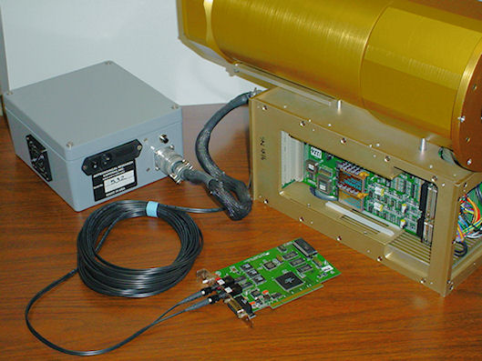
The major elements of the system are as follows:
- The large, nearly cylindrical gold colored object on the right is a liquid nitrogen dewar held under vacuum that is used to keep the CCD cold during operation.
- It is mounted to a housing containing controller boards, shown with two of its panels remove for visibility and access. Connecting wires between the CCD and the controller boards can be seen to the far right of the figure.
-
This is the ARC-45 CCD video board that processes readout channels of the CCD. Behind this video board are located a ARC-32 clock driver board and a ARC-22 timing board, with all three boards plugged into the controller backplane.
-
The grey box to the left is the ARC-81 power supply, supplying the DC power to the controller through the large black cable with circular aluminum connectors at each end.
-
The small board in front is the ARC-64 PCI interface that accepts digital image data from the controller over the black fiber optics cable shown coiled up and writes them to the host computer.
1.2.1. ARC-22 - 250 MHz Fiber Optic Timing Board
-
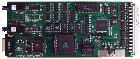
- The 250 MHz fiber optic timing board performs three main functions
- communicating between the controller and the host computer PCI interface board: duplex fiber optic link at a bit rate of 250 MHz providing a data transfer rate of 12.5 Mpixels per second
- generating timing waveforms by writing 16-bit digital words as often as every 40 nanoseconds over a backplane to other controller boards
- providing overall controller supervision such as exposure timing, power sequencing, controlling a shutter, and synchronizing operations with signals external to the controller using the Motorola DSP56003 Digital Signal Processor, operating at an internal clock speed of 100 MHz
1.2.2. ARC-32 - CCD Clock Driver Board
-
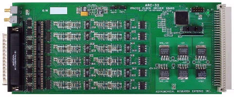
- The clock driver board translates digital input signals into analog output signals for direct connection to CCD array. It provides 24 clock signals, each of which has programmable high and low voltages. Their rise and fall times can be adjusted by inserting resistors and capacitors in the output circuit. This board will drive up to +/- 13 volts for operating CCD arrays.
1.2.3. ARC-45 - Dual Readout CCD Video Board
-
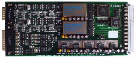
- The dual readout CCD video processing board serves two functions - processing and digitizing video outputs from two CCD video channels and supplying DC bias voltages to the CCD. Two 16-bit analog-to-digital (A/D) converters simultaneously digitize signals from two video outputs at a maximum pixel rate of 1 MHz. The DC bias supply section of the board provides ten low noise, digitally programmable voltage outputs with a variety of voltage ranges suitable for direct connection to CCDs. There is a three op amp differential input circuit on each of the two video processors, suitable for connection to the outputs of preamps located next to the CCD that drive long cables. There is also a single ended circuit that can be connected directly to the CCD video output pin.
1.2.4. ARC-64 - 250 MHz PCI Interface Board
-
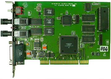
- The 250 MHz PCI interface board provides communication and data transfer between the host computer and the controller. Connection to the controller is via a fiber optic cable, which provides a maximum sustained data transfer rate of 12.5 Megapixels/second. It writes large images directly to system memory using a DMA capability. It can be used in PCI backplanes that supply either 3.3 or 5 volt power.
1.2.5. ARC-81 - Small Power Supply
-
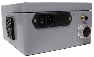 The small power supply provides DC to smaller systems. It also contains a driver for solenoid type shutters. ||Voltage output: ||+5, ±6.5, ±16.5, +36, +12(fan) volts ||
 Available power:
20 watts per supply

