Installation problems
20061014  created AB
      16  more noise meaurements AB
/net/obssf6/export/diskC1/home_instrum/T120/WWW/INSTRUMENTATION/C2controleur/MISSION_SILLA/INSTALLATION_PROBLEMS.html
Readout Noise
This is the main problem. The overall readout noise is summarized below.
  mode INT_TIM  pixel_time noise system   gain
                   [musec]  [e]  noise[e] [e/ADU]
  ---- -------  ---------- ----- -------- -------
  fast $200000       4.52   20    3.7      1.8
  slow $7F          12.12   15    1.9      4.5
System noise was measured with controller + preamplifier with signal input grounded. When we connected the CCD but still with signal input grounded the noise did not increased substantially. With previous system we had the noise 8e in "slow" mode. On the BIAS images appears a high frequency noise. We do not have real features at specific frequency but some frequency appears with period of approx. 11 pixels of 12.12 [musec] i.e 7.5 kHz.
Two cables between the preamplifier and the dewar separe the "static + signal" and "dynamic (clocks)" voltages. The signal has not separate shielding and could catch the noise of static voltages.
The power supply produces noise up to 100 e if close to the dewar. We had to put it on the outskirt of the instrument.
In order to clarify the source of the noise we did following measurements summarized below. All measurement were made with short and long integration constant of the integrator which has no effect on the result (and insure that the gain calibration is consistent). The chip is not connected.
                                                                         noise ratio
    # conditions                                                   mode noise[e] slow/fast
    - ----------------------------------------------------         ---- -------  ---------
    1 controller only                                              fast    1.3
                                                                   slow    0.9      1.4
    2 controller+preamp. VOD grounded                              fast    3.7
                                                                   slow    1.9      1.9
    3 controller+preamp. VOD N.C.                                  fast    8.0
                                                                   slow    4.4      1.8
    4 controller+preamp. VOD coupled to RD via 100nF               fast    21
                                                                   slow    21       1.0
    5 controller+preamp. VOD coupled to Last Gate via 100nF        fast    11
                                                                   slow    11       1.0
    6 controller+preamp. VOD coupled to Output Drain via 100nF     fast    34
                                                                   slow    28       0.8
While in measurements #1-3 the ratio between the noise in slow and fast mode which should be for the white noise (t-slow/t-fast)**0.5 ~ 2 is close to that value, the noise on the voltages lines is not. It points to the noise bandwith related to the sampling frequency. The power spectrum of fast readout and slow readout have similar shape with an additional LF noise in fast mode corresponding to the variation of the average BIAS well visible on the horizontally averaged overscan.
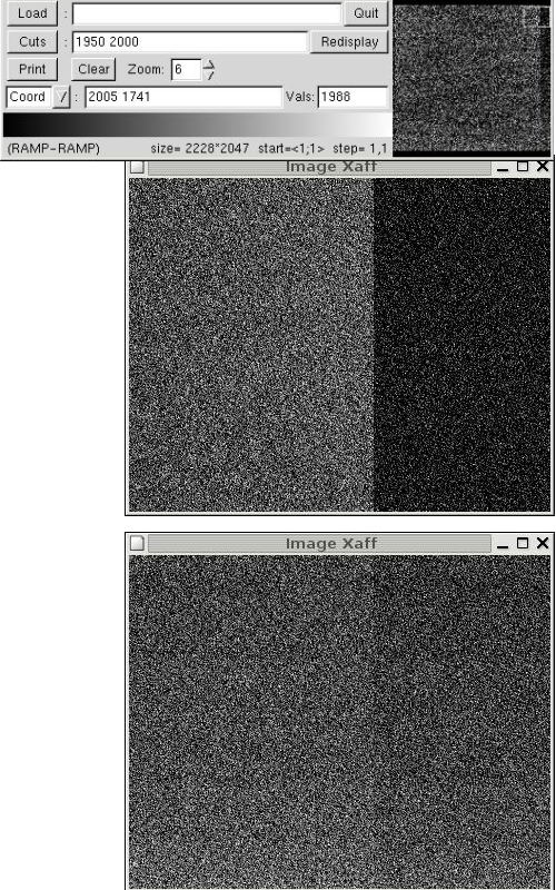
BIAS level variation
The overscan is not at the same value (which was the case on the DC coupled old system) and the difference between the level of the active area and the overscan vary "vertically" from almost nothing at first rows to ~ 30e at the top.
Waveforms
We cannot obtain P-clock waveforms clock overlap of 0.8 [milisec] as specified by SITe because the limitation in the timing. We used the longest delay possible
P_DELAY	EQU	$FF0000  gives 127*0.32*5=40.64 [musec] per state

and we repeated each state in the waveforms 5x to get the clock overlap of 0.2 [millisec]


PARALLEL_UPPER
	DC	END_PARALLEL_UPPER-PARALLEL_UPPER-1
	DC	CLK3+P_DELAY+P1+P2+00+00
	DC	CLK3+P_DELAY+P1+P2+00+00
	DC	CLK3+P_DELAY+P1+P2+00+00
	DC	CLK3+P_DELAY+P1+P2+00+00
	DC	CLK3+P_DELAY+P1+P2+00+00
	DC	CLK3+P_DELAY+00+P2+00+00
	DC	CLK3+P_DELAY+00+P2+00+00
	DC	CLK3+P_DELAY+00+P2+00+00
	DC	CLK3+P_DELAY+00+P2+00+00
	DC	CLK3+P_DELAY+00+P2+00+00
	....

END_PARALLEL_UPPER
The P-clocks at the input to the dewar cable look well and are similar of what we got on Astrocam controller.
We use the same Serial clocksin slow and fast mode generated by the sequence as provided in the original SITe424tim.waveforms:
SERIAL_READ_RIGHT
    DC    END_SERIAL_READ_RIGHT-SERIAL_READ_RIGHT-1
    DC    CLK2+S_DELAY+RG+S1+S2+00+00
    DC    VIDEO+$000000+%1110100        ; Change nearly everything
    DC    CLK2+S_DELAY+RG+S1+00+00+00
    DC    CLK2+S_DELAY+00+S1+00+S3+SW
    DC    CLK2+S_DELAY+00+00+00+S3+SW
    DC    CLK2+S_DELAY+00+00+S2+S3+SW
    DC    CLK2+S_DELAY+00+00+S2+00+SW
    DC    $00F041                       ; Transmit A/D #1 data to host
    DC    VIDEO+$000000+%1110111        ; Stop resetting integrator
    DC    VIDEO+$000000+%1110111        ; Additional settling time
    DC    VIDEO+INT_TIM+%0000111        ; Integrate '-' with inverted polarity (offset)
    DC    VIDEO+$000000+%0011011        ; Stop Integrate
    DC    CLK2+S_DELAY+00+00+S2+00+00    ; Charge dump from summing well
    DC    VIDEO+$000000+%0011011        ; Delay for signal to settle
    DC    VIDEO+$000000+%0011011        ; Delay for signal to settle
    DC    VIDEO+INT_TIM+%0001011        ; Integrate '+' with non-inverted polarity
    DC    VIDEO+$000000+%0011011        ; Stop integrate, A/D is sampling
END_SERIAL_READ_RIGHT
(see also the complete configuration file) These clocks are slightly faster but very similar to clocks on Astrocam system. Slowing the clock down does not help. There is a very shallow minimum in noise at the serial clock state duration (S_DELAY=$0A0000) which gives the clock 3-state cycle duration of 1.2 [musec].
Video processing
We tried various modifications of the readout and we checked that the video board has signals at appropriate timing and levels. At the beginning of theIntegration Video period the signal (yellow) seems noisy. We introduced tentatively delays between the switching (blue trace changes the polarity) and the actual integration with no effect.
Other problems
The programmable offset interval is not sufficient. With the high programmable gain of 10 we are out of 0-64000 and the image is either 0 or 2**16-1. It prevents the good measurement of the system noise.
After the reload of the DSP program (tim.lod) the controller takes approx. 60 seconds to stabilize. It devaluates completely the rapidity of the download. Presently we must reload when switching from fast to slow (INT_TIM in waveforms changes).